


Uncategorized
EM385 Programmable Power Supply Self-Diagnostic Guide
Have you ever encountered issues during vehicle diagnostic programming, such as sudden voltage drops that cause the ECU to “brick,” or long diagnostic or programming sessions that drain the battery and trigger the ECU’s protection mode? In such cases, having a stable diagnostic programming power supply becomes absolutely essential. In this blog, we’ll address common feedback and issues related to mobile programmable power supplies.
1.Unstable Power Supply Voltage
Issue Symptoms
- The diagnostic tool cannot connect to the ECU, or the connection is frequently lost.
- Interruptions occur during programming, causing ECU flashing to fail (potentially leading to a “bricked” ECU).
- Malfunctioning vehicle electronic modules (such as the BCM or ECU) may exhibit abnormal behavior, including data corruption or functional failures.
Possible Causes
- Fluctuations in output voltage (e.g., dropping below 12V or rising above 14V).
- Insufficient power output (e.g., sudden increase in current demand during ECU programming).
- Poor connection in power supply wiring (e.g., loose alligator clips or poor grounding).
Solutions
- Verify Power Supply Current Output:Check that your power supply can deliver at least 30A of current. For certain ECU programming operations, you may need an even higher current capacity.
- Properly Ground the Negative Terminal:Always connect the power supply’s negative terminal to a clean, unpainted metal surface on the vehicle chassis. Avoid attaching it to corroded or oxidized areas of the battery’s negative terminal.
2.Reverse Polarity Connection
Issue Symptoms
- The diagnostic device or ECU may not respond, and in severe cases, smoke, burn out, or cause the vehicle’s fuse to blow.
Possible Causes
- The power supply’s positive and negative leads are connected incorrectly (red to negative, black to positive).
- An inferior power supply is used that lacks reverse polarity protection.
Solutions
- Use a power supply with reverse polarity protection (EM365/385 models come with built-in reverse polarity protection, which effectively prevents this issue).
- Before connecting, use a multimeter to confirm the polarity (red for positive, black for negative). If the polarity is reversed, immediately disconnect the power and check the ECU and diagnostic device for any damage.
3.Insufficient Power Supply Causing ECU Reset
Issue Symptoms
- The ECU suddenly loses power during programming, causing the flashing process to fail (potentially “bricking” the ECU).
- The vehicle’s dashboard flickers, and the ECU enters protection mode.
Possible Causes
- Insufficient power output (e.g., the instantaneous current demand during ECU programming exceeds the power supply’s limit).
- Unexpected power consumption from other vehicle modules (such as lights or fans).
Solutions
- Turn off all vehicle electrical devices (headlights, air conditioning, audio system, etc.).
- Use a high-current power supply (≥30A) to ensure stable voltage.
- Some high-end models (e.g., BMW, Mercedes) may require an external battery to maintain power supply.
4.Power Supply Incompatibility with Vehicle
Issue Symptoms
- The diagnostic device cannot access certain ECUs (such as the transmission control unit (TCU) or ABS module).
- The vehicle enters “transport mode” or “sleep mode” and cannot be awakened.
Possible Causes
- Some vehicle models (e.g., Volkswagen, Audi) require precise voltage (13.5V) to enter diagnostic mode.
- New energy vehicles (e.g., Tesla, BYD) may use high-voltage systems (48V or 400V), which cannot be supported by standard 12V power supplies.
Solutions
- Consult the vehicle’s service manual to confirm the ECU wake-up conditions.
- For new energy vehicles, use a dedicated power adapter (such as an EVSE power supply).
5.Power Supply Overheat or Overload Protection
Issue Symptoms
- The power supply automatically shuts off and cannot provide continuous power.
- The power supply fan runs at high speed, and the casing becomes hot.
Possible Causes
- Prolonged high-load operation (e.g., ECU programming lasting more than 10 minutes).
- Excessive ambient temperature (e.g., in-vehicle temperatures exceeding 40°C during summer).
Solutions
- Choose a power supply designed to handle sustained high-load operation.
- Use the power supply in a well-ventilated environment to prevent overheating.
About AUTOOL Programmable Power Supply FQAs
1. What is the amperage under the Programmable Power Supply power supply mode?
In programming mode, the maximum output current can reach up to 150A.
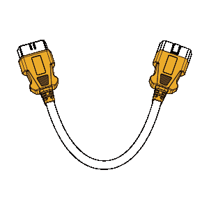
Can the clamp cables of the diagnostic programming power supply be extended?
Yes, we support custom 3-meter and 5-meter clamp cables. However, these need to be shipped from China. If you’re interested, please contact our. online support >>
Is the jump-start current/voltage 400A/12V? Will repeated jump-starting cause any risk, such as burned wires?
Yes, the maximum jump-start current is 400A at 12V. The jump-start current is instantaneous—it does not remain at 400A continuously. Our wiring has been reinforced to prevent wire burning.
6.Summary: How to Properly Use an Programmable Power Supply
Choose the Right Power Supply
- Voltage: 13.5V ± 0.5V (some vehicle models require precise adjustment).
- Current: ≥30A (higher current may be needed during ECU programming).
Ensure Stable Connections
- Connect the positive terminal to the battery’s positive post (or the OBD power port).
- Connect the negative terminal to a good ground point on the vehicle chassis (avoid oxidized areas).
Minimize Interference
- Use a linear power supply or install a filter.
- Turn off all vehicle electrical devices (e.g., headlights, air conditioning, audio system).
Special Vehicle Considerations
- New-energy vehicles: Use a dedicated high-voltage power adapter.
- High-end brands (e.g., BMW, Mercedes): An external battery may be required to keep the system powered.
Using the power supply correctly can greatly improve diagnostic and programming success rates while preventing ECU damage! 🚗💻
 AUTOOL Official Team
Mobile/whatsapp/Wechat:+86 189 2647 7404
Email: shop.autooltech.com
Website Official Shop: https://shop.autooltech.com/