


Uncategorized
Easily Solve Common Electronic Control System Issues
“When you are driving at high speed and suddenly see the [Drive System Failure] red alarm, the center control screen starts flashing, and the vehicle power gradually disappears… This is not a movie plot, but a real encounter of Mr. Li, a Tesla owner in Shanghai. The diagnostic solution provided in this article easily solved the electronic control system failure, allowing him to lock the source of the failure within 20 minutes and avoid ten thousand dollars of repair costs”.
Core principles of the electronic control system
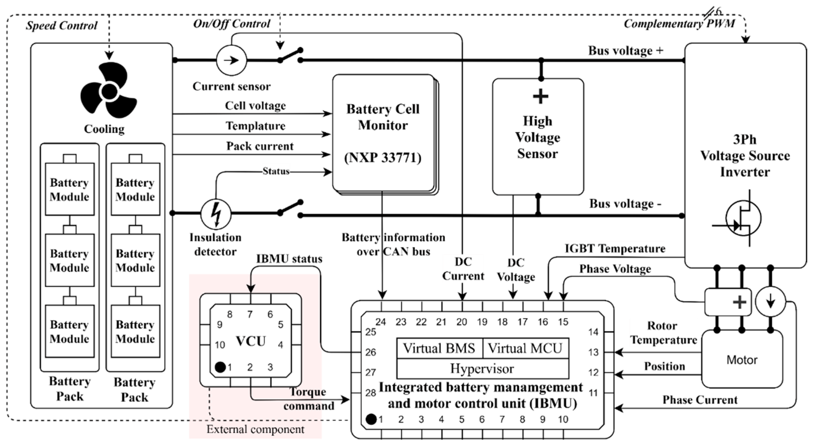
The electronic control system is the “brain” of an electric vehicle, responsible for controlling the work of several important components, including the battery management system (BMS), motor control unit (MCU), vehicle control unit (VCU), etc. They work together to ensure the stable operation of the vehicle’s power output, charging management, power distribution, braking system, and so on. They work together to ensure the stable operation of the vehicle’s power output, charging management, power distribution, braking system, and so on. Taking our human body as an analogy, to put it simply: VCU = brain (decision-making center) | MCU = spinal cord (command transmission) | BMS = liver (energy metabolism).
Common electronic control system failures are usually found in the following areas:
- Battery Management System (BMS) malfunction
- Motor Control Unit (MCU) malfunction
- Vehicle Control Unit (VCU) malfunction
- Abnormal or overloaded voltage
|
Failure phenomenon |
primary investigation point |
owner self-inspection method |
repair store test item |
|
power suddenly interrupted |
12V small battery voltage |
with a USB voltage detector to measure the cigarette lighter |
VCU power supply relay impedance test |
|
charging gun can not be unplugged |
electronic locking mechanism |
emergency pull rope position schematic diagram |
CP signal waveform analysis |
|
energy recovery system failure |
wheel speed sensors |
observation of the tire pressure monitoring data |
braking energy recovery MAP map calibration |
Electronic Control System Troubleshooting Process
| Fault type | common trouble | Diagnostic steps | Solutions |
| Battery Management System (BMS) Failure | Inaccurate display of power level, charging abnormality | Reading OBD fault codes | Repair battery connections or replace damaged batteries |
| High temperature warning light on, battery overheating | Check for loose battery connections | Replace BMS if necessary | |
| Battery Health Status Detection | |||
| Motor Control Unit (MCU) failure | Unresponsive acceleration or power lag | Read MCU fault codes | to fix power or signal line faults |
| Abnormal motor heat or loss of power | Check the motor and its connections | Check cooling system | |
| Motor load check | Replace the motor if necessary | ||
| Vehicle Control Unit (VCU) Malfunction | The vehicle loses power, and won’t start | Scan for VCU fault codes | Software upgrade or reset |
| Fault light long on or flashing | Try the electronic control system restart Replace | VCU unit if necessary | |
| Check VCU input voltage | Check battery pack voltage stability | ||
| Abnormal voltage or overload fault | Battery voltage is too low or too high | Monitor battery voltage fluctuations | Adjust the output current of the charging equipment |
| Electrical control system overload protection | Check the status of the charging system | Check the battery charging and discharging conditions to avoid overcharging or over-discharging |
Hierarchical Diagnostic Guidelines
Owner’s Edition
Applicable Scenarios: Sudden appearance of malfunction warning light, power abnormality or system error report while driving.
1. Golden 5-minute operation
steps:
- ① Emergency stop: Immediately turn on the dual flashers, slowly apply the brakes to move the vehicle to a safe area (avoiding ramps and curves), and if there is a complete loss of power, press and hold the “P” button to force the vehicle to stop.
- ② Fault Message Recording: Take a picture of all warning lights on the instrument panel, ensuring time stamps are included. Record the actions before the malfunction occurred (e.g., had you just finished charging or been driving aggressively?). Additionally, check the “Vehicle Status” page on the center control panel and take screenshots to save key data such as battery temperature, SOC value, and motor speed.
- ③ Basic Environmental Inspection: Check for any burning smell or liquid leakage in the cabin (avoid touching the orange high-voltage harness), and use a cellphone flashlight to inspect the chassis for cuts, especially around the battery pack location.
2. Emergency restart program (forced reset operation)
Applicable situations: the car machine is dead, the dashboard is garbled, function buttons malfunction, and other soft faults.
Universal program:
- Double insurance restart method:
a. Disconnect the low-voltage power supply: open the trunk, find the negative terminal of the 12V small battery (labeled “-”), use a 10mm wrench to disassemble and wait for 5 minutes. b. Long-press the “car machine power button + volume knob” and then press the “car machine power button + volume knob”.
b. Long press the “car power button + volume knob” for 15 seconds (double scroll wheel long press for Tesla Model 3).
c. Reconnect the battery and start the vehicle to see if the problem is eliminated.
Vehicle specific:
- Azera ES6: Press and hold the steering wheel “Menu + Volume Down” buttons at the same time until the logo appears (about 20 seconds)
- Ideal ONE: There is a physical button for “Forced Reboot” in the passenger compartment (needs to be triggered with a card pin)
Risks:
- Perform forced reboot up to 3 times per month ( Frequent power cuts may damage the memory)
- If the “Maximum Speed Limit” message appears after a reboot, you need to have it serviced in a store immediately
Technician’s Edition
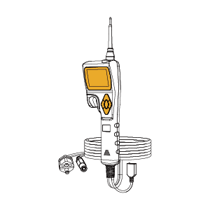
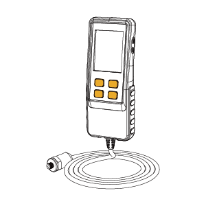
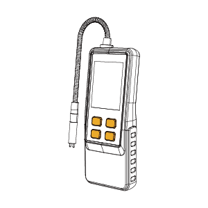
1. Waveform Analysis Method (Oscilloscope Practical Skills)
Core applications: Detecting motor rotation signals, CAN bus waveforms, and PWM drive pulses.
Case: Determine motor rotation sensor failure
- Normal waveform characteristics: Sine and cosine waveforms are symmetrical in amplitude (typical value: 2.5V ± 0.2V), with a strictly maintained phase difference of 90 degrees (deviation >5° is abnormal).
- Faulty waveform identification: Waveform aberration may indicate a broken sensor ring, requiring motor disassembly for inspection, while signal interruption suggests checking the sensor power supply line (normal voltage: 5V ± 0.1V).
2. Data tracing technique (charging/discharging curve analysis)
Diagnostic logic: locate hidden faults through historical data.
Operation Procedure:
- Export BMS charging data (focus on timestamp, unit voltage, temperature cluster)
- Generate a “Voltage-Time” curve with Excel and observe the amount of mutation:
◦ Normal curve: voltage rises smoothly, the voltage difference between neighboring units <30mV
◦ Signs of fault: voltage drop of a specific unit >100mV (may be loosening of connecting tabs)
- Cross-comparison of charging pile logs (get real-time current/voltage via Modbus protocol) Cross-comparison of charging pile logs (obtaining real-time current/voltage via Modbus protocol)
3. Stress test program (extreme working condition verification)
Purpose: To reproduce the occasional failure and verify the repair effect.
IGBT Module Temperature Rise Test Procedure:
1. Connect a thermal imager (FLIR E8 recommended) and align it with the motor controller heat sink
2. Activate the “Full Load Mode” using the diagnostic instrument (simulate continuous acceleration from 0-100km/h for 10 times)
3. Monitor the key parameters:
◦ IGBT junction temperature ≤150°C (exceeding 170°C triggers the overheating protection)
◦ Three-phase current balance (difference <5%)
Safety Specifications:
– HV insulation monitoring device (e.g. KEW 3125) must be installed before the test
– Test environment temperature control at 25±3°C (avoid external interference)
Cross-version common precautions
– Points for collaboration between owner and technician:
◦ Make sure to provide a complete record of fault-triggering conditions when handing over the vehicle
◦ Prohibit the owner from clearing the fault codes by himself (critical diagnostic data will be lost)
– Red lines for high-risk operations:
◦ Direct contact with high-voltage components without insulated gloves (even if de-energized)
◦ Use of a non-isolated power supply to power the vehicle controller (may cause a short-circuit ) ◦ Using a non-isolated power supply for the on-board controller (may cause a short circuit)
How to prevent the failure of the electronic control system?
- Regular inspection: Regular inspection and maintenance of the electronic control system, especially the key components such as BMS, MCU, VCU, etc., to ensure stable operation of the system.
- Keep clean: Sensors, battery interfaces, and motor interfaces of the electronic control system should be kept clean to avoid dust or moisture intrusion leading to failure.
- Update the software in time: Make sure the software version of the electronic control system is up-to-date, and the manufacturer will launch repair programs and function optimization regularly.
Conclusion
Electronic control system failures aren’t impossible to fix. With basic fault code reading, system checks, and simple maintenance, vehicle owners and technicians can quickly identify and resolve common issues to keep the vehicle running smoothly. Learning these essential diagnostic skills helps you handle problems with ease and prevent more serious damage.